This is based on July’s IFT ZK Call. Visit the IFT ZK Meeting Notes for additional resources, and the video link.
Circuits, often, come in two flavors: arithmetic and boolean.
- An arithmetic circuit have gates that consist of field operations.
- A Boolean circuit uses logic gates such as AND and XOR.
The majority of circuits assume that each gate has two inputs and one output. Theoretically, this is not a necessary requirement but this is a reasonable assumption.
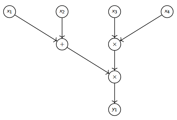
The following circuit represents y_1 = (x_1 + x_2)\cdot(x_3 \cdot x_4).
Why arithmetic circuits?
Zero-knowledge proofs can be used to convince any verifier of a given claim. However, the validity of a claim is based on a given context. Arithmetic circuits serve as this context (relation).
An arithmetic circuit provides the explicit relationship between the public claim (statement) and the Prover’s secret data (witness).
In terms of the circuit above, I could say “I know values that produce y_1 = 21 in the circuit above.” The statement would be y_1 = 21, the relation is the arithmetic circuit, and my witness could be x_1 = 2, x_2 = 5, x_3 = 1, x_4 = 3.
A Verifier knows the circuit and the claim, but not my witnesses. Instead, a zero-knowledge proof is provided to convince the Verifier that my claim is true.
This is how zk-SNARKs and circuits relate.
Circuit representation
There are multiple ways that a circuit can be represented: R1CS, SAP and Plonkish.
R1CS
R1CS or the long version of the name, Rank-1 constraint system, is a popular circuit that is used in Bulletproofs. R1CS is related to the circuit representation quadratic arithmetic program (QAP). QAPs were used for Pinocchio and Groth16; due to this, some will say that these zk-SNARKs use R1CS.
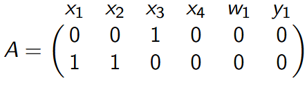
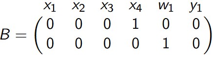
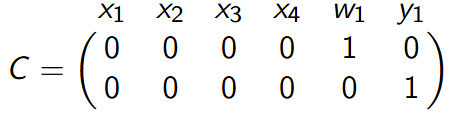
R1CS constructs a matrices A, B, and C:
- A represents the left inputs for multiplication gates.
- B represents the right inputs for multiplication gates.
- C represents the output for gates.
The addition gates are collapsed into the rows of the multiplication gates. That is, C is a quadratic from the multiplication of A and B.
For our example,
Squaring arithmetic program (SAP)
A squaring arithmetic program represents arithmetic circuits with addition gates and squaring gates.
- a + b
- a^2 = a \cdot a
Each multiplication gate can be represented as a combination of squaring gates and addition gates as follow: a \cdot b = \frac{(a + b)^2 - (a-b)^2}{4}. This conversion increases n multiplication gates to at most 2n squaring gates.
Squaring arithmetic programs have been used for Pari and Polymath. Both of these zk-SNARKs are notable as these both result in a concrete decrease in proof size compared to Groth16. Groth16 is the state-of-the-art proof size in terms of only group elements construction for pairing based SNARKs. However, Pari and Polymath achieve smaller sizes in terms of bytes.
Plonkish
Plonkish representation are used by Plonk and Halo2. Plonkish allows for custom gates of the form:
q_L \cdot a + q_R \cdot b + q_M \cdot (a\cdot b) - q_O \cdot c + q_K = 0.
This allows Plonkish circuits to support addition, multiplication, squaring, and Boolean gates.
| gate | q_K | q_{L} | q_R | q_O | q_M |
|---|---|---|---|---|---|
| + | 0 | 1 | 1 | 1 | 0 |
| \times | 0 | 0 | 0 | 1 | 1 |
| XOR | 0 | 1 | 1 | 1 | -2 |
Across each gate, the values q_K, q_L, q_R, q_O and q_M form vectors. Thus, the entire circuit can be represented as a matrix equation in which a, b and c are replaced by matrices.
Conclusion
The circuit representation may appear arbitrary. This is due to their abilities to represent any arithmetic circuit. The “correct” circuit representation to use is dependent on zk-SNARK selection and a constraint generator that you may use.